|
|
 03 February 2014, 12:55
|
#41
|
|
Member
Join Date: Jul 2011
Posts: 874
|
Marked the engine mounting plate with duct tape.
Piece that is marked with tape will be cut off to allow better water clearance.
Box section hanger to be cut and internal sleeve to be fitted to section with engine plate.
This will slide into box section of the bracket more or less allowing the unit to be split in half.
To secure it I will drill it and use stainless bolts to hold together.
This will allow engine plate to be removed for towing and storage etc.
An inch and a half section to be removed from box section when cut is made.
This is to get engine plate closer to the tube and improve water clearance whilst sib making turn to the left. 
__________________
|

|

|
|
03 February 2014, 13:01
|
#42
|
|
RIBnet Supporter
Country: Ireland
Length: 4m +
Join Date: Feb 2008
Posts: 14,684
|
Quote:
Originally Posted by kaman

Whole unit seemed solid.  |
Because it's on dry land.
At sea, the tube handle and transom bracket are not fixed positions, relative to each other.
This will not end happily.
__________________
I'm sorry, but there IS no Mars Bar.
|
|
|
|
|
03 February 2014, 13:25
|
#43
|
|
Member
Join Date: Jul 2011
Posts: 874
|
Quote:
Originally Posted by willk
Because it's on dry land.
At sea, the tube handle and transom bracket are not fixed positions, relative to each other.
This will not end happily.
|
What's the tube handle?
__________________
|
|
|
|
|
03 February 2014, 13:32
|
#44
|
|
Member
Join Date: Jul 2011
Posts: 874
|
Cancel.
I've sussed that you mean the handle on the dinghy.
I could use the underside of the engine plate as an anchor point instead it isn't going to flex or move.
__________________
|
|
|
|
|
03 February 2014, 16:29
|
#45
|
|
Member
Country: UK - England
Town: St Ives
Boat name: Jessy
Make: Seago
Length: under 3m
Engine: honda 2.3
Join Date: Jan 2014
Posts: 29
|
The prop looks awfully close to your tubes.
__________________
|
|
|
|
|
03 February 2014, 17:06
|
#46
|
|
Member
Join Date: Jul 2011
Posts: 874
|
Quote:
Originally Posted by jep49
The prop looks awfully close to your tubes.
|
Hi Jep, it does in one of the photos, but I think it is just the angle of the picture.
There is plenty of room on the engine mounting plate to move the engine closer or further away from the tubes see attached. It can go close as long as it don't touch / shred it I'll be fine
__________________
|
|
|
|
|
03 February 2014, 17:17
|
#47
|
|
Member
Join Date: Jul 2011
Posts: 874
|
Rod holders
Made some brackets a few years ago to mount rod holders .
I utilised the pre drilled holes with eyelets to hold the rod holder plates in position. I didn't meant to drill four self tapping screws into transom.
I have altered it slightly to mount on the engine mount.
They really are handy bits of kit for fishing from a Sib 
__________________
|
|
|
|
|
03 February 2014, 17:19
|
#48
|
|
Member
Join Date: Jul 2011
Posts: 874
|
Quote:
Originally Posted by kaman
Made some brackets a few years ago to mount rod holders .
I utilised the pre drilled holes with eyelets to hold the rod holder plates in position. I didn't meant to drill four self tapping screws into transom.
I have altered it slightly to mount on the engine mount.
They really are handy bits of kit for fishing from a Sib |
Above should read - I didn't want to drill holes for four self tapping screw into the transom.
Me and my sausage fingers!!!
__________________
|
|
|
|
|
03 February 2014, 17:30
|
#49
|
|
Member
Join Date: Jul 2011
Posts: 874
|
Previously looked like this prior to engine mount.
I have two rod holders which are set in a metal bracket.
The bracket is screwed into the underside of the seat.
A rod can be seen in the picture sitting in one of the rod holders.
Invaluable pieces in a small fishing Sib in my opinion
__________________
|
|
|
|
|
03 February 2014, 20:02
|
#50
|
|
Member
Country: UK - England
Town: St Ives
Boat name: Jessy
Make: Seago
Length: under 3m
Engine: honda 2.3
Join Date: Jan 2014
Posts: 29
|
Hi,
I am planning to make a set of wheels for the transom of my 2.7 sib. They look expensive for what they are to buy. They look flimsey too, And because my little honda rotates 360 degrees they would get in the way of the handle. So using my previous skill as a welder i plan to make some with a tube sliding within a slightly larger one. Figured it out , just looking for the tube.
__________________
|
|
|
|
|
03 February 2014, 20:20
|
#51
|
|
Member
Join Date: Jul 2011
Posts: 874
|
Quote:
Originally Posted by jep49
Hi,
I am planning to make a set of wheels for the transom of my 2.7 sib. They look expensive for what they are to buy. They look flimsey too, And because my little honda rotates 360 degrees they would get in the way of the handle. So using my previous skill as a welder i plan to make some with a tube sliding within a slightly larger one. Figured it out , just looking for the tube.
|
Mines are three year old now and made of aluminium.
Since I built a trailer 2 years ago I only use them to wheel the boat off of my trailer into the water, and vice versa.
Don't think they would hold up too long bumping around rough ground with 150 kg of engine, gear and Sib bearing down on them.
They are however more robust than they look.
Mines were around 60 quid, for that money I can't fault them.
__________________
|
|
|
|
|
04 February 2014, 12:56
|
#52
|
|
Member
Country: UK - England
Town: St Ives
Boat name: Jessy
Make: Seago
Length: under 3m
Engine: honda 2.3
Join Date: Jan 2014
Posts: 29
|
i shall have to make it from mild steel, because easier to get hold of and weld. Got the wheels from a lawnmower. About 2 quid i think., and strong.
__________________
|
|
|
|
|
04 February 2014, 15:11
|
#53
|
|
Member
Join Date: Jul 2011
Posts: 874
|
Quote:
Originally Posted by jep49
i shall have to make it from mild steel, because easier to get hold of and weld. Got the wheels from a lawnmower. About 2 quid i think., and strong.
|
Cool.
Mild steel will do the job.
Just be mindful that inflatable fat tyres work best.
The thinner and harder they are the more they sink into sand / shingle etc.
I changed the standard 2.5 inch tyres that came on mine to 3 inch wide variants.
The 3 inch tyres perform much much better.
__________________
|
|
|
|
|
04 February 2014, 15:17
|
#54
|
|
Member
Country: UK - England
Town: St Ives
Boat name: Jessy
Make: Seago
Length: under 3m
Engine: honda 2.3
Join Date: Jan 2014
Posts: 29
|
I have four of about 8 inches by one and a half. Bit over the top, but i could use all four. Bit like the back wheels of a aggregate lorry. lol
__________________
|
|
|
|
|
14 February 2014, 07:23
|
#55
|
|
Member
Country: UK - England
Town: Essex
Make: Quicksilver
Length: 4m +
Engine: 30hp
Join Date: Feb 2014
Posts: 132
|
All very interesting. Thanks for a great thread. We obviously all go through these processes of what if. I've just bought a 3.3 mariner 2 stroke as my aux to accompany my 30hp on a quicksilver 430hd, for those further afield trips. We all seem to get braver and go further off shore. I now use a depth finder, tablet as a chart plotter, have a vhf radio etc etc. Also just bought a Muck Truck to pull it down the beach!
Now I just have to work out where to put it, started with google and voila!
I would love to see how Guanard has attached his to the transom, I assume with one of those lifting aux brackets? I don't really want to lose the transom wheels though, so was wondering about making a bracket that suspended the aux above one of the tubes that could not work in that position but if needed could be lifted off. That would either involve lifting off the 30hp (52kg) which might not be that easy, or maybe removing one of the transom wheels and connecting a removable transom bracket for its use. I'm not fishing near rocks so there is no time limit /rush and anchoring up wouldn't be a problem because its rarely more than 40'. Sods law says that when you need it, a hooly would have just kicked in! I do like 'Kamans' bracket though. Might be worried if the sea got big in case a wave caught it, but I would never plan to be out in those sorts of conditions, although waves do get big very quickly when off shore I have found out.
Also what are the rollers Gurnard referred to please? They sound handy.
Thanks for any input
__________________
|
|
|
|
|
14 February 2014, 17:46
|
#56
|
|
Member
Country: UK - Scotland
Town: Stirling
Boat name: The Gurnard
Make: Quicksilver
Length: 4m +
Engine: mariner 25hp 2s
Join Date: Jul 2013
Posts: 1,653
|
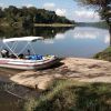
Hi Bass Stalker
I just mount the aux engine to the transom as shown. I protect the transom from the screw downs with a sheet of aluminium.
I had to remover the corner flap that stops water spray but I never get any thrown up from the 25Hp engine so it wasnt an issue.

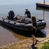
Only photo I have handy of the roller boats is this one of my hardshell boat. You can see one under the rear of the boat to roll it into the water... saves trailer wheels getting dipped in salt water.

You inflate them and can roll the boat along on two of them. I just lift the bow..shove one under..pivot the stern on the rollerboat and push...once you have two under..its easy pushing.... when one comes out the back..just lift it up and reposition under the front again and shove till the next one comes out the back.
Good thing is ..they take up little space deflated ..so are always in the box at the front of my boat.. ready to inflate when I need them
You can get them here at 20 squids for one that will hold 400Kg weight.
Force 4 Inflatable Boat Roller - 400kgs - 160x25cm - Only £19.95 - Force 4 Chandlery
__________________
|
|
|
|
|
14 February 2014, 19:47
|
#57
|
|
Member
Country: UK - England
Town: Essex
Make: Quicksilver
Length: 4m +
Engine: 30hp
Join Date: Feb 2014
Posts: 132
|
Superb. Thank you 'The Gurnard' for your reply. The picture shows it perfectly. Is that the 2.5 or 3.3? Is it standard shaft, I assume enough is in the water? Haven't tried it on the boat yet, I assume it will push it along nicely.
The rollers look a clever idea. Had no idea they existed. Funny also how you have some extra wheels added to your trailer. I have a set in the garden and was going to do exactly the same, so I could drag the trailer out when recovering if shallow for long way, so as not to dip the muck truck.
Just have to decide now whether to ditch the transom wheels, hmm.
Thanks again
__________________
|
|
|
|
|
15 February 2014, 00:10
|
#58
|
|
Member
Country: UK - England
Town: South Coast
Make: Quicksilver
Length: 3m +
Engine: outboard
Join Date: Feb 2006
Posts: 142
|
I see your also a fan of the sub £20 B&Q sack trolley. They are fantastic value, I have a couple, I have one to store and move the outboard. One I cut down for a kayak tug and one I cut down for a dinghy launch trailer, cheapest way to get wheels for your boat.
__________________
|
|
|
|
|
15 February 2014, 06:56
|
#59
|
|
Member
Join Date: Jul 2011
Posts: 874
|
I do like 'Kamans' bracket though. Might be worried if the sea got big in case a wave caught it, but I would never plan to be out in those sorts of conditions, although waves do get big very quickly off shore I have found out.
Not done anything more with the bracket lately but I'm nightshift this week and plan to do the following modifications to it.
Cut through the 50mm box section - cutting unit in half.
Weld a sleeve into the half to which the engine mounts.
Drill two holes in the box section on the half that mounts to transom.
Drill sleeve with two corresponding holes
M8 stainless bolts to be used to secure both halves of the unit together.
Trim down engine mounting plate to improve clearance from the water.
Paint with hardened grey marine paint.
I've had a few concerns during this project.
Most have been resolved apart from that regarding the water clearance of the unit.
I am satisfied that the unit and transom are robust enough to do the job.
At present the engine mounting plate measures 150mm (15cm) top to bottom.
50mm (5cm) of this is in the 50mm square box section which sits above the top of the tube.
This leaves 100mm (10cm) sticking downwards - potentially in the way of the splish splash waves.
The overall diameter of the tubes are 450mm (45cm).
Having studied a few YouTube videos of similar Honwaves on the move in the chop the splash up at the rear comes up to the underside of the rear carry handles.
This unit is mounted slightly higher than the top edge of the rear carry handle.
As I sit at the opposite side of the boat (right) when using the Honwave this slightly tilts the boat to the right elevating the auxiliary engine side (left) upwards and further clear of the water.
The aux engine and main engine both short shafts.
The aux has been deliberately mounted approx 120mm higher than the main to aid water clearance.
As I will be transferring my weight to the left tube when using the aux this has the affect of tilting the Honwave to the left, lowering the aux into the water.
I often go out with a mate but they tend to sit on the seat up front which has a custom made leather cushion.
As they tend to sit in the middle they have no affect on the camber of the Honwave.
I can alter the height of the aux mount by building it up and trimming the lower edge to improve water clearance further.
Time and sea trailing will tell.
Worst case scenario if it does not work to plan and I can't leave the aux mounted whilst out at sea.
I will wrap and strap the aux down inside the Honwave along with the engine mounting plate.
Clip on a safety lanyard to the aux to prevent it going over the side when clamping it onto the aux mount.
I will post pictures of finished mods in the next fortnight or so.
__________________
|
|
|
|
|
15 February 2014, 07:05
|
#60
|
|
Member
Join Date: Jul 2011
Posts: 874
|
I do like 'Kamans' bracket though. Might be worried if the sea got big in case a wave caught it, but I would never plan to be out in those sorts of conditions, although waves do get big very quickly off shore I have found out.
Not done anything more with the bracket lately but I'm nightshift this week and plan to do the following modifications to it.
Cut through the 50mm box section - cutting unit in half.
Weld a sleeve into the half to which the engine mounts.
Drill two holes in the box section on the half that mounts to transom.
Drill the sleeve with two corresponding holes
M8 stainless bolts to be used to secure both halves of the unit together.
Trim down engine mounting plate to improve clearance from the water.
Paint with hardened grey marine paint.
I've had a few concerns during this project.
Most have been resolved apart from that regarding the water clearance of the unit.
I am satisfied that the unit and transom are robust enough to do the job.
At present the engine mounting plate measures 150mm (15cm) top to bottom.
50mm (5cm) of this is in the 50mm square box section which sits above the top of the tube.
This leaves 100mm (10cm) sticking downwards - potentially in the way of the splish splash waves.
The overall diameter of the tubes are 450mm (45cm).
Having studied a few YouTube videos of similar Honwaves on the move in the chop the splash up at the rear comes up to the underside of the rear carry handles.
This unit is mounted slightly higher than the top edge of the rear carry handle.
As I sit at the opposite side of the boat (right) when using the Honwave this slightly tilts the boat to the right elevating the auxiliary engine side (left) upwards and further clear of the water.
The aux engine and main engine both short shafts.
The aux has been deliberately mounted approx 120mm higher than the main to aid water clearance.
As I will be transferring my weight to the left tube when using the aux this has the affect of tilting the Honwave to the left, lowering the aux into the water.
I often go out with a mate but they tend to sit on the seat up front which has a custom made leather cushion.
As they tend to sit in the middle they have no affect on the camber of the Honwave.
I can alter the height of the aux mount by building it up and trimming the lower edge to improve water clearance further at a later date if need be.
Worst case scenario if it does not work to plan and I can't leave the aux mounted whilst out at sea.
I will wrap and strap the aux down inside the Honwave along with the engine mounting plate.
I will clip on a safety lanyard to the aux to prevent it going over the side when clamping it onto the aux mount.
This way I will have a readily available back up as in my opinion there is no way you can lift a 50kg plus motor into a Sib at sea, and all but the simplest of repairs have to be done on dry land.
Time and sea trialing will tell.
I will post pictures of finished mods in the next fortnight or so do some trials and take it from there, fingers crossed!
__________________
|
|
|
|
|
|
 Posting Rules
|
You may not post new threads
You may not post replies
You may not post attachments
You may not edit your posts
HTML code is Off
|
|
|
|
 Recent Discussions
 |
|
|
|
|
|
|
|
|
|
|
|
|
|
|
|
|
|
|
|
|
|
|
|
|
|
|
|
|
|
|
|
|
|