|
|
 06 March 2004, 17:34
|
#1
|
|
Member
Country: UK - England
Town: Lymington
Boat name: Lynx 1, 2, 3
Make: Scorpion
Length: 8m +
Engine: Mercury 275
Join Date: Aug 2002
Posts: 182
|
Battery Selector Switch
Hi All,
Does anyone have any details on how you wire one of the above in? I would rather make sure before I go attaching anything!!
I believe that the two positive leads from the two batteries go to the back of the switch and the two neg leads join the two batteries together.
What and where does the next lead come from to connect to the third point on the back of the switch??
Any help would be great. A picture would be even better.
Thanks
Stuart
__________________
|

|

|
|
06 March 2004, 17:56
|
#2
|
|
Member
Country: UK - England
Town: Devon
Boat name: White Ice
Make: Ranieri
Length: 5m +
Engine: Suzuki 115hp
Join Date: Jul 2002
Posts: 5,015
|
Quote:
Originally posted by scm
What and where does the next lead come from to connect to the third point on the back of the switch??
|
That's the +ve supply to engine, fusebox, gadgets, etc.
Easiest way to do this is to locate the switch within reach of your original big red lead, so you simply remove this from the original (single) battery and attach it to the "output" terminal of the switch (assuming the eyelet/terminal post will fit!). Then fit red leads from the positive of each battery to the "input" posts on the switch. Finally, the negatives both go to your old black neg lead.
If you get it all in place, measure up the length of cables required and go to a motor electrical fitter to get these cables made up and soldered (unless anyone knows better - ie can you get tinned cable in this size?)
|
|
|
|
|
06 March 2004, 17:56
|
#3
|
|
Member
Country: UK - England
Town: Herne Bay
Boat name: Rotary Rescue
Make: Pacific 22
Length: 6m +
Engine: Mermaid 160
MMSI: 235021725
Join Date: Nov 2003
Posts: 328
|
Batt Switch
Pos from each bat goes to 1 & 2. The last one is the common going to the engine, all other12v circuits should come off of this pole aswell.The only one going direct from batts is supply to bilge pump if fitted to allow it to run in auto whilst bat switch off.Negs together or to bus bar.
Do you have a split charger system fitted(blocking diodes) fitted??If you dont then you will need it.
Hope that helps
Paul
__________________
|
|
|
|
|
06 March 2004, 18:14
|
#4
|
|
Member
Country: UK - England
Town: Devon
Boat name: White Ice
Make: Ranieri
Length: 5m +
Engine: Suzuki 115hp
Join Date: Jul 2002
Posts: 5,015
|
SCM - apologies if this is obvious, but only conect one battery positive direct to the bilge pump - otherwise you'll bypass the switch and probably burn the leads out!
Also - you don't need a split charger system if you're prepared to charge just one battery at a time, but they are a good idea. I didn't fit one to the hard boat when I did this upgrade, and probably won't fit one to Blue Ice if/when I get round to the dual battery upgrade.
I wonder how many RIBs with a dual batteries have a split charger system?
|
|
|
|
|
06 March 2004, 18:49
|
#5
|
|
Member
Country: UK - England
Town: Herne Bay
Boat name: Rotary Rescue
Make: Pacific 22
Length: 6m +
Engine: Mermaid 160
MMSI: 235021725
Join Date: Nov 2003
Posts: 328
|
batt switch
Richard
can see where you are coming from.might have had my hard boat head on. But if one was fitted at least you wouldnt have to worry about charging and should you need the other battery at least it will be fully charged.We have one on our hard boat and it has worked to our favour a couple of times.
Paul
__________________
|
|
|
|
|
06 March 2004, 18:56
|
#6
|
|
Member
Country: UK - England
Town: Lymington
Boat name: Lynx 1, 2, 3
Make: Scorpion
Length: 8m +
Engine: Mercury 275
Join Date: Aug 2002
Posts: 182
|
Guys,
Many thanks for those replys. You have confirmed what i thought, however, it is always nice to get someone to confirm them.
I am not sure about the split charger, i am happy to charge each battery in turn. ie one day bty 1 the next day bty 2. But here what you say.
I will use this opertunity to sort out the bildge pump that has been left wired from when it sat on a pontoon!!!
By the way the only reason for doing this is that to code your boat it states you must have an alt bty fitted.
Regards
Stuart
|
|
|
|
|
07 March 2004, 00:32
|
#7
|
|
Member
Country: UK - Scotland
Make: HumberOceanOffshore
Length: 8m +
Engine: Volvo KAD300/DPX
Join Date: Oct 2002
Posts: 5,596
|
If you don't want to fit a diode, why don't you set the switch onto the 'Both' position and charge both batteries together?
__________________
JW.
|
|
|
|
|
07 March 2004, 05:59
|
#8
|
|
Member
Country: UK - England
Town: Devon
Boat name: White Ice
Make: Ranieri
Length: 5m +
Engine: Suzuki 115hp
Join Date: Jul 2002
Posts: 5,015
|
Being cautious by nature, I never used the "both" position in case the non-identical batteries set up their own circuit, but I guess that if they are both in reasonable condition, this should be OK. However, if they're not, then surely this would discharge the good battery before charging them both?
|
|
|
|
|
07 March 2004, 07:25
|
#9
|
|
Member
Country: UK - England
Town: Herne Bay
Boat name: Rotary Rescue
Make: Pacific 22
Length: 6m +
Engine: Mermaid 160
MMSI: 235021725
Join Date: Nov 2003
Posts: 328
|
bat switch
your right in what your saying richard, not only that if you had a problem then you could drain both,which defeats the object of having 2 batts. The voltage regulator on some models would detect voltage of a full batt and one batt may be slightly down so therefore wouldnt get a full charge, catch 22 i beleive??
__________________
|
|
|
|
|
07 March 2004, 09:15
|
#10
|
|
Member
Country: UK - England
Town: Cippenham
Boat name: Falcon1
Make: Falcon
Length: 6m +
Engine: 115hp Mariner Four S
MMSI: 235021077
Join Date: Jun 2003
Posts: 508
|
I would think you may be safer getting someone to check a diagram of what you are thinking of doing before you connect up as you are dealing with very large currents and you could easily have a fire on your hands if you get it wrong. you will be better fitting a blocking diode as if one battery is flat it will run down the other if they are just connected together. good luck
__________________
|
|
|
|
|
07 March 2004, 12:40
|
#11
|
|
Member
Country: UK - Scotland
Make: HumberOceanOffshore
Length: 8m +
Engine: Volvo KAD300/DPX
Join Date: Oct 2002
Posts: 5,596
|
No it won't. It'll transfer charge until both batteries are at the same potential. If the batteries are not under load at the time, this is not likely to be too much of a problem. The two batteries will, between them, contain the same energy (minus a tiny bit during the transfer). A problem would arise if one battery were damaged and was not able to reach the potential of the other.
However, since a switch is being fitted, I presume it will be used. Putting the switch onto the 'both' setting can be done before starting the engine and, once the engine is started, both batteries will be receiving a charge. If, when leaving the boat, the switch is moved to the off position, there won't be a problem, even with a damaged battery. Having said that, what is the point of keeping a damaged battery on the system?
Richard's point about not jumping the positives for the purpose of supplying the bilge pump, is a good one as is Chris's point about drawing a diagram and looking for errors before you get near to the actual wiring up
My own preference is to use a switch but, also, to add another in the form of the screw type battery isolator which is commonly fitted to cars as an accessory. These fit into the negative battery post. I use one battery as the main supply, fit the isolator to the other, and I bridge the isolator with a schottky diode. The isolator is then left open. The switch is set to 'both' during use and both batteries will charge.
Whether the engine is running or not, the main battery is the one in use because the diode blocks the second one from discharging. Should the first battery become discharged or damaged, closing the isolator will give a fully charged battery, ready for service.
If it's a discharge situation, once the engine is running, opening the isolator will allow the the system to revert to normal and the discharged battery will recharge as normal.
The use of a schottky diode limits the voltage drop for charging and ensures the backup battery reaches a good state of charge. The normal limits for the voltage regulator are 13.7v to 14.2v so the 0.4v loss in the diode is more than tolerable. Unless you've got a lowish output from the regulator,  then the whole system will be a bit down.
These things always sound more complicated by description than they actually are.
Go slowly, take care to search out any errors and it'll be fine.
__________________
JW.
|
|
|
|
|
07 March 2004, 13:57
|
#12
|
|
Member
Country: UK - England
Town: Devon
Boat name: White Ice
Make: Ranieri
Length: 5m +
Engine: Suzuki 115hp
Join Date: Jul 2002
Posts: 5,015
|
JW - intersting idea - if I understand correctly you're describing a basic split charge system to allow the 2nd battery to charge only through the schottky diode when the additional isolator is closed, and provide additional EMF when the additional isolator is closed?
Just to build things up slowly, here's a diagram of the basic setup which I described earlier (without JW's enhancements)...
|
|
|
|
|
07 March 2004, 14:00
|
#13
|
|
Member
Country: UK - England
Town: Devon
Boat name: White Ice
Make: Ranieri
Length: 5m +
Engine: Suzuki 115hp
Join Date: Jul 2002
Posts: 5,015
|
And here's what I think JW is suggesting (hope I've got the diode the right way round!)
JW - what I'm not familiar with is the type of isolator you're describing (why not use a marine one, they aren't expensive?) and the schottky diode - is that just a high current type?
|
|
|
|
|
07 March 2004, 15:37
|
#14
|
|
Member
Country: UK - Scotland
Make: HumberOceanOffshore
Length: 8m +
Engine: Volvo KAD300/DPX
Join Date: Oct 2002
Posts: 5,596
|
Nope, Richard, that's not what I'm suggesting. I suppose I'd better draw a diagram. 
I've not seen a marine version of the isolator. I don't think there would be any difference, except cost.
__________________
JW.
|
|
|
|
|
07 March 2004, 15:42
|
#15
|
|
Member
Country: UK - England
Town: Devon
Boat name: White Ice
Make: Ranieri
Length: 5m +
Engine: Suzuki 115hp
Join Date: Jul 2002
Posts: 5,015
|
Quote:
Originally posted by jwalker
I've not seen a marine version of the isolator. I don't think there would be any difference, except cost.
|
Like this - is the car one similar? http://marinestore.co.uk/Merchant2/m...egory_Code=els
|
|
|
|
|
07 March 2004, 15:48
|
#16
|
|
Member
Country: UK - Scotland
Make: HumberOceanOffshore
Length: 8m +
Engine: Volvo KAD300/DPX
Join Date: Oct 2002
Posts: 5,596
|
Nope, but you could use one of those if you prefer.
Actually, I've also used the circuit I described without the 3 way switch and just switched it on or off using one of those.
---
Edit... Tell yer wot, I'll go and take a snap of my batteries.
__________________
JW.
|
|
|
|
|
07 March 2004, 16:53
|
#17
|
|
Member
Country: UK - Scotland
Make: HumberOceanOffshore
Length: 8m +
Engine: Volvo KAD300/DPX
Join Date: Oct 2002
Posts: 5,596
|
Circuit diagram.
__________________
JW.
|
|
|
|
|
07 March 2004, 16:55
|
#18
|
|
Member
Country: UK - Scotland
Make: HumberOceanOffshore
Length: 8m +
Engine: Volvo KAD300/DPX
Join Date: Oct 2002
Posts: 5,596
|
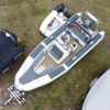
Batteries.
Not quite as clear as I'd hoped.
__________________
JW.
|
|
|
|
|
07 March 2004, 17:02
|
#19
|
|
Member
Country: UK - Scotland
Make: HumberOceanOffshore
Length: 8m +
Engine: Volvo KAD300/DPX
Join Date: Oct 2002
Posts: 5,596
|
Isolator. The diode is soldered to the connector under the red tape - blue cable to other end.
Looking at that pic, I suppose I should have used black tape on the end of that negative battery cable. Slap me wrist. The Blue knob at the rear makes/breaks the connection. This type is not so common, they usually have the knob on the top. (No comments please.)
__________________
JW.
|
|
|
|
|
07 March 2004, 17:16
|
#20
|
|
Member
Country: UK - England
Town: Devon
Boat name: White Ice
Make: Ranieri
Length: 5m +
Engine: Suzuki 115hp
Join Date: Jul 2002
Posts: 5,015
|
Nice one JW. I guess the blue wire only carries charging current, hence the thinner cable. But why the thin black wire? I expected to see something like this on the (switched) red side for bilge pump(s)? And can you elaborate on the "schottky diode"?
|
|
|
|
|
|
 Posting Rules
|
You may not post new threads
You may not post replies
You may not post attachments
You may not edit your posts
HTML code is Off
|
|
|
|
 Recent Discussions
 |
|
|
|
|
|
|
|
|
|
|
|
|
|
|
|
|
|
|
|
|
|
|
|
|
|
|
|
|
|
|
|
|
|