Reply
 
Thread Tools Search this Thread
 
Old 28 September 2018, 08:05   #1
Member
 
SimonStDavids's Avatar
 
Country: UK - Wales
Town: St Davids
Boat name: Mellifera
Make: Avon
Length: 4m +
Engine: Outboard
Join Date: May 2010
Posts: 189
RIBase
Yamaha trim sender wiring

I am hoping I can pick the collective brains of the forum regarding some old Yamaha electronics.

I have an old (1989) Yamaha 50DETO and as part of my winter work I am trying to hook up a multifunction gauge I picked up from eBay to the engine.

I will add some pictures when I get home but I can’t any part numbers on anything!

What I have-

-Yamaha 50DETO and 703 control box
-Goosed (I think)4 wire trim sender
-LCD multi functional gauge
- 2 x wiring harnesses (one for trim and one for oil level)

I have hooked the tacho part of the gauge and it works fine but I am struggling with the rest!!!

With the trim sender, from what I can gleam from the internet is

Orange- 5v reference feed
Black- Ground
Pink- signal to gauge
Grey- ?

I have got 5v from the gauge on the orange and getting about 3.5v on the pink, the voltage doesn’t vary as the arm moves so hence I am guessing it is goosed. Does anyone know or remember what the range of voltage from sender should be?

Does anyone know what the grey wire is? At the other end of the harness is a plug, three wires go to the gauge (black, pink and orange) and the grey go to a bullet connection that is connected to anything?

Oil level, the harness has a plug the gauge end and a male and female bullet connectors the other end. There is no obvious termination for these the engine end but from what I can gather, if I splice these onto the two wires from the oil tank sender then it should work?

If anyone can shed some light on any of the above it would be most appreciated.

Simon
__________________
SimonStDavids is offline   Reply With Quote
Old 28 September 2018, 12:15   #2
Member
 
SimonStDavids's Avatar
 
Country: UK - Wales
Town: St Davids
Boat name: Mellifera
Make: Avon
Length: 4m +
Engine: Outboard
Join Date: May 2010
Posts: 189
RIBase
Here is the trim wiring harness, two of the bullet connectors have come off but before they came off the wires matched four wires from the sender.

Click image for larger version

Name:	IMG_0616.jpg
Views:	3398
Size:	260.6 KB
ID:	127038

The plug the gauge end matches a plug from the back of the gauge. As mentioned above, the grey doesn’t go into the gauge but terminates in a bullet connector.

Click image for larger version

Name:	IMG_0617.jpg
Views:	933
Size:	301.8 KB
ID:	127039

The oil harness is similar to the trim harness, plug at one end and connectors the other.
__________________
SimonStDavids is offline   Reply With Quote
Old 30 September 2018, 07:18   #3
Member
 
boristhebold's Avatar
 
Country: UK - England
Length: 7m +
Join Date: Aug 2009
Posts: 1,619
Perhaps the grey wire goes to a common negative bus.

Probably what might help is if you create a schematic diagram and add each component, item model, wires/colours and connectors etc we may be able to help.
__________________
boristhebold is offline   Reply With Quote
Old 30 September 2018, 07:22   #4
Member
 
boristhebold's Avatar
 
Country: UK - England
Length: 7m +
Join Date: Aug 2009
Posts: 1,619
something like this may help
Attached Thumbnails
Click image for larger version

Name:	6d3cb70f9d0bae8a4a4eb7c0caeb4652.jpg
Views:	13693
Size:	54.7 KB
ID:	127101  
__________________
boristhebold is offline   Reply With Quote
Old 30 September 2018, 07:26   #5
Member
 
boristhebold's Avatar
 
Country: UK - England
Length: 7m +
Join Date: Aug 2009
Posts: 1,619
or this
Attached Thumbnails
Click image for larger version

Name:	yamaha-outboard-control-wiring-diagram-no-power-crank-the-hull-truth-boating.jpg
Views:	16419
Size:	113.0 KB
ID:	127102  
__________________
boristhebold is offline   Reply With Quote
Old 30 September 2018, 17:32   #6
Member
 
Tim M's Avatar
 
Country: France
Town: Côte d'Azur
Boat name: Beaver Patrol
Make: Avon Searider SR4
Length: 4m +
Join Date: Jan 2004
Posts: 5,934
The trim sender is a rheostat; it works by changing the resistance in the circuit which is what the gauge recognises. So switch your multimeter to resistance from voltage. Second, I believe your model of trim sender is actually only two wires (forgotten the colours for now). You will most probably have spare wires on your loom that don't do anything.
__________________
Tim M is offline   Reply With Quote
Old 30 September 2018, 19:10   #7
Member
 
SimonStDavids's Avatar
 
Country: UK - Wales
Town: St Davids
Boat name: Mellifera
Make: Avon
Length: 4m +
Engine: Outboard
Join Date: May 2010
Posts: 189
RIBase
Thanks all, Boris the second image is pretty close to what I have but I can’t find where to connect the oil harness engine end? I have tried searching the internet for an adapter but so far have drawn a blank??

Tim- I think way back in the day Yamaha wanted to be different and so pre 1993 had a 3 wire system that used variable voltage. I don’t think it was a great system as after 1993 all the senders became 2 wire ones like the rest of the industry!

I will take some images of the gauge tomorrow and see if I can draw a schematic of what I have...

Thanks so far though
__________________
SimonStDavids is offline   Reply With Quote
Old 30 September 2018, 19:34   #8
Member
 
Country: UK - Scotland
Town: wormit
Boat name: lots of them
Make: various
Length: no boat
Engine: all types
Join Date: Dec 2004
Posts: 618
Quote:
Originally Posted by SimonStDavids View Post
Thanks all, Boris the second image is pretty close to what I have but I can’t find where to connect the oil harness engine end? I have tried searching the internet for an adapter but so far have drawn a blank??

Tim- I think way back in the day Yamaha wanted to be different and so pre 1993 had a 3 wire system that used variable voltage. I don’t think it was a great system as after 1993 all the senders became 2 wire ones like the rest of the industry!

I will take some images of the gauge tomorrow and see if I can draw a schematic of what I have...

Thanks so far though
The green and the green with the red tracer connects onto the oil level sensor. It should also have a black that goes to ground/earth. Does your tacho have a grommet in the back with dip switches?

As far as fitting the trim sender unit, your sender unit with the 4 bullet connections is for the analog 2” gauge and I don’t think it is compatible with the digital bar graph trim gauge/Rev counter. I know from years back when the digital rev counters came available we had to fit the matching trim senders.
__________________
Davie is offline   Reply With Quote
Old 01 October 2018, 20:12   #9
Member
 
SimonStDavids's Avatar
 
Country: UK - Wales
Town: St Davids
Boat name: Mellifera
Make: Avon
Length: 4m +
Engine: Outboard
Join Date: May 2010
Posts: 189
RIBase
Thanks Davie, I have been down to the boat today to try and make sense of it all and I have taken some bad photos. But I think you are right, I am not convinced this gauge is going to fully work with what I have. I also couldn’t find any dip switches either, just the pole section switch?

I have hooked up the trim sender and measured the voltages.

Orange 5v
Pink 3.7v regardless of where the arm is so I guessing isn’t working.

With the gauge connected up to the sender it shows as fully trimmed out, well all the bars are lit anyway. If I connect it to the grey (less than 1v) it shows almost fully trimmed in.

Now that I am pretty sure the sender is broken I am wondering whether it is either possible to add a newer 2 wire sender and gauge or look to replace like for like?

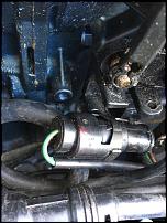
For the oil level, I found the wires Davie mentioned and traced the green pair to the plug in the photo, by touching the male bullet connectors against either pin in the plug the gauge would change oil level indication, so I think if I just splice the harness onto these wires at least that should work!

Click image for larger version

Name:	IMG_0621.jpg
Views:	2024
Size:	131.1 KB
ID:	127135
__________________
SimonStDavids is offline   Reply With Quote
Old 02 October 2018, 20:40   #10
Member
 
Country: UK - England
Make: Ribcraft
Length: 5m +
Engine: Yamaha
Join Date: Feb 2006
Posts: 309
Quote:
Originally Posted by Davie View Post
The green and the green with the red tracer connects onto the oil level sensor. It should also have a black that goes to ground/earth. Does your tacho have a grommet in the back with dip switches?

As far as fitting the trim sender unit, your sender unit with the 4 bullet connections is for the analog 2” gauge and I don’t think it is compatible with the digital bar graph trim gauge/Rev counter. I know from years back when the digital rev counters came available we had to fit the matching trim senders.
The old trim senders are certainly compatible with the later digital tachometers- I am using a 1987 four wire sender on my 70hp with a 6YR tachometer and matching Fuel Management (later early/mid 2000s type with resettable hour meter but before the separate trim and oil looms were integrated into one loom).
__________________
phantom 19 is offline   Reply With Quote
Reply

Tags
yamaha

Thread Tools Search this Thread
Search this Thread:

Advanced Search

Posting Rules
You may not post new threads
You may not post replies
You may not post attachments
You may not edit your posts

BB code is On
Smilies are On
[IMG] code is On
HTML code is Off
Trackbacks are Off
Pingbacks are Off
Refbacks are Off


All times are GMT. The time now is 18:14.


Powered by vBulletin® Version 3.8.8 Beta 1
Copyright ©2000 - 2024, vBulletin Solutions, Inc.