|
|
 07 December 2005, 21:11
|
#181
|
|
Member
Country: UK - England
Town: helston
Boat name: pressman
Make: Carson 900
Length: 9m +
Engine: twin 370 yanmar
Join Date: Jul 2005
Posts: 373
|
Sorry Paul 
__________________
|

|

|
|
07 December 2005, 21:17
|
#182
|
|
Member
Country: UK - Wales
Town: Southampton
Boat name: DynaMoHumm/ SRV/deja
Make: Avon8.4, 5.4 & 4.777
Length: 8m +
Engine: Cat3126 Yam 90 &70
MMSI: 42
Join Date: Dec 2003
Posts: 6,562
|
I think the engine/drive combination might work well as the jet will be possibly more robust than a bravo 3x
what's the weight of the boat please I imagine the Power to weight ratio is quite good
__________________
Here it comes again, I don't stand a chance
Soul possession, Got me in a trance
Pullin' me back to you - Deja Voodoo
|
|
|
|
|
07 December 2005, 21:19
|
#183
|
|
Member
Country: UK - England
Town: helston
Boat name: pressman
Make: Carson 900
Length: 9m +
Engine: twin 370 yanmar
Join Date: Jul 2005
Posts: 373
|
It's 3 tonne with no fuel, carries 1300 litres
__________________
|
|
|
|
|
07 December 2005, 21:25
|
#184
|
|
Member
Country: UK - England
Town: Brittany/Portsmouth
Boat name: Merlin
Make: Solent 6.5
Length: 6m +
Engine: 200
MMSI: soon !
Join Date: Jul 2003
Posts: 5,451
|
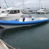
heres the best i got of the jet drive itself

and it on the go

and another

__________________
Happy New Resolutions!!! : RIBbing for the craic!!!
|
|
|
|
|
07 December 2005, 21:29
|
#185
|
|
Member
Country: UK - England
Town: Brittany/Portsmouth
Boat name: Merlin
Make: Solent 6.5
Length: 6m +
Engine: 200
MMSI: soon !
Join Date: Jul 2003
Posts: 5,451
|
Looks cool Steve & Caroline 
Especially slicing throught the water like that !
missus
__________________
Happy New Resolutions!!! : RIBbing for the craic!!!
|
|
|
|
|
07 December 2005, 21:32
|
#186
|
|
Member
Country: UK - England
Town: helston
Boat name: pressman
Make: Carson 900
Length: 9m +
Engine: twin 370 yanmar
Join Date: Jul 2005
Posts: 373
|
Next time Kathleen 
__________________
|
|
|
|
|
07 December 2005, 21:36
|
#187
|
|
Member
Country: UK - England
Town: Brittany/Portsmouth
Boat name: Merlin
Make: Solent 6.5
Length: 6m +
Engine: 200
MMSI: soon !
Join Date: Jul 2003
Posts: 5,451
|
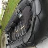
from the stern
how many ltr a second would each engine be pushing through at full blast

paul
__________________
Happy New Resolutions!!! : RIBbing for the craic!!!
|
|
|
|
|
07 December 2005, 21:39
|
#188
|
|
Member
Country: UK - England
Town: helston
Boat name: pressman
Make: Carson 900
Length: 9m +
Engine: twin 370 yanmar
Join Date: Jul 2005
Posts: 373
|
Cool Pics guys, tried to send you a PM But  ............
__________________
|
|
|
|
|
07 December 2005, 21:39
|
#189
|
|
Member
Country: UK - England
Town: Brittany/Portsmouth
Boat name: Merlin
Make: Solent 6.5
Length: 6m +
Engine: 200
MMSI: soon !
Join Date: Jul 2003
Posts: 5,451
|
Quote:
|
Originally Posted by pressman
Next time Kathleen |
Excellent.
Mind you, looks like himself had fun at the helm.
Many thanks Steve
K & P
Will get round to pms soon.ta
__________________
Happy New Resolutions!!! : RIBbing for the craic!!!
|
|
|
|
|
23 May 2006, 15:17
|
#190
|
|
Member
Country: USA
Town: Annapolis MD
Length: 6m +
Join Date: Aug 2005
Posts: 10
|
More Jet Drive info
Quote:
|
Originally Posted by Mollulnan
Lets face it a waterjet aint very complicated. It's bloody harder to drive one than understand how it works!
|
Well not quite so. To really get the most out of them there remains some new work to attend to.
Quote:
|
Originally Posted by Milan
....can some one tell me and this may end up being a really stupid QUESTION but is the flow of water through the intake regulated and at what point because it seems to me the faster the boat travels the faster the water should be taken in and in that case bearing in mind that the way this thing works is a fast jet of water being expelled from the rear then at greater speed a lot of the work is already done and the engine should become more economical....
|
First part you got right....need some sort of regulation of inlet. Second part wrong
Quote:
|
Originally Posted by DJL
As far as I know boat jet units won't suck water into the jet unit if they are full of air - the impellors are the wrong shape to shift the air out the back efficiently.
Therefore the jet unit needs to be full of water for it to work.
In rough water if the boat leaves the water and the jet unit empties, the water has to make its way back into the jet unit on its own (via gravity/mass/force or pressure - however you want to look at it), its not 'sucked' in by the impellor/engine. Hence you get a period without thrust while you wait for the water to make its way back in.
Props (on outboards etc) on the other hand are in instant contact with the water when the boat return from flight - no need to wait for air to clear.
|
You got a lot of it right.
Quote:
|
Originally Posted by DGR
Sucking = low pressure, so water travels towards the low pressure. Can we therefore agree that the impeller, which produces a low pressure area, draws water into the intake?
Where I disagree is on the nozzle. If the nozzle is only directional, why is the impeller not just a propeller in a tube? The jetski impellers I've seen are centrifugal - why is that? The only reason I can think of is that it needs to generate higher pressures, to give higher velocities in the outlet. To do that, it must accelerate through a nozzle - so surely it must be shaped with a constriction?
|
The jet pump does suck water in, even when it is 'out of the water' And the nozzel is not just a directional item, but rather important to the operation of the jet pump.
Quote:
|
Originally Posted by DGR
The water ceases to be a pressure chamber and becomes the bullet as it goes through the nozzle. The job of the nozzle is to convert pressurised water into high speed water, i.e. Potential Engery to Kinetic Energy, where velocity (squared) has a big effect.
I think the nozzle is the most important bit of the water jet - without it, you don't get any increase in velocity through the unit (as water is incompressible), so there won't be any significant change in momentum. The impeller would act like a really crap propeller in a tube. As water goes through the nozzle, the pressure drops to atmospheric at the throat (narrowest bit), whilst accelerating the waterstream to its highest velocity at the point where the pressure returns to normal - making the momentum per second (i.e. force) the biggest at the point at which it leaves the jet.
|
YES
Quote:
|
Originally Posted by DGR
Kind of - but the impeller isn't axial like a prop.
Props and jets all use mV to produce force to drive a boat. Axial (conventional) props move both mass and increase velocity to provide the force. A jet moves less mass, but more velocity to achieve the same thing.
|
Actually the impeller is more axial than a prop
Quote:
|
Originally Posted by jwalker
My conclusion from this was that there needs to be something moving and in the waterjet is has to be water.
The waterjet needs to be able to hold water at a high pressure to provide the propulsive force and so it cannot simply be an open tube. Also we need to get the moving water (the bullet) to store as much energy as possible. The stored energy is going to be largely wasted out the back. Kinda like the bullet after it's left the barrel.
The way to get the energy into the water is to increase its velocity. Also, the more mass of water we can increase the velocity of, the better because it will store more energy. However, there will be a limit to the mass of water that can be got moving because if the hole out of which the water is flowing gets too big, the pressure inside the jet will begin to fall and it's this pressure which will make the boat move forward.
Enter, the nozzle. The nozzle and the taper before it is the device which is going to accelerate the water to increase its velocity and, hence, absorb energy at this end of the system. This is the bullet. So, now we've got something for the pressure at the forward end of the jet to react against. Of course, because the water jet is capable of drawing in water, it is able to constantly replenish the bullet. In turn, the boat will absorb the energy imparted to it and also store some of it.
|
YES
I found a number of these discussions interesting. I thought some of you might find these additional discussions on the YachtForums.com site interesting as well, Jet Drive vs Prop . There are additional discussions on varible inlets and advanced nozzles from the webmaster who is extremely knowledgeable about the subject from both military and commerical experience. There is also some as rim-drive impeller suggestions I introduce.
(for some reason I couldn't make the links, as that tool bar was not available to me??)
|
|
|
|
|
23 May 2006, 20:08
|
#191
|
|
Member
Country: Other
Length: 6m +
Engine: 200
Join Date: Apr 2004
Posts: 344
|
Informative Brian!
After this thread we travelled to Ireland on a mighty jet drive Ferry.
Nice to watch the thing really power up and go for it.
Us
__________________
Joint Ribtickler 2005
|
|
|
|
|
24 May 2006, 00:39
|
#192
|
|
Member
Country: UK - England
Town: Nottingham
Length: no boat
Join Date: Feb 2006
Posts: 238
|
WOW, how long did thiis thread last????? When i got to about page two i check my fluid mechanics book on the shelf to make sure i knew what i was on about, but by the time i got to page 20 it seemed any reply would be a bit pointless!
Hope you finally sorted it out JW
__________________
|
|
|
|
|
24 May 2006, 02:55
|
#193
|
|
Member
Country: USA
Town: Annapolis MD
Length: 6m +
Join Date: Aug 2005
Posts: 10
|
Jet-Pump Fundamentals
As I took another look at what I had done in referencing these other discussions, I thought the better of it, and figured there were probably a number of people who might not be that interested in that much detail to track thru the other sites. So maybe just posting here some basic discussion from those sites would suffice.
Quote:
|
Originally Posted by YachtForums
Let me begin with some jet-pump fundamentals...
To better understand how the intake gullet works, we need to take a closer look at the jet-pump and the impeller. The impeller itself will only scatter water, and is highly inefficient. But, when placed within a "shrouded" environment, it becomes a ducted propeller. This shrouded configuration produces greater efficiency than its open, non-shrouded counterpart. The reason is simple. The duct controls water and forces it backwards as opposed to a propeller which allows water to slip outwards.
Impellers (and jet-pumps) work on the principal of positive and negative pressure, or a push/pull concept. As a blade rotates, it pushes water back (and outwards due to centrifugal and accelerated force). At the same time, water must rush in to fill the space left behind the blade. This results in a pressure differential between the two sides of the blade: a positive pressure, or pushing effect on the blade face and a negative pressure, or pulling effect, on the backside of the blade. This action occurs on all the blades around the full circle of rotation.
Thrust is created by water being drawn into the impeller and accelerated out the back. However, due to the spiraling effect (vortex) of water leaving the trailing edge of the blade it must pass through stators (straightening vanes) to "true" its trajectory. Stators also increase velocity by "catapulting" water, similar to the way a "kick" works on the trailing edge of a propeller blade. To further enhance velocity, water passes through the venturi before finally exiting the pump as thrust. As we discussed earlier, the venturi works on the principle that a restriction or reduction in line size will cause water to accelerate if the same volume is to be realized at the other end of the restriction. This is where you get the "jet" in pumps. Finally, a steering nozzle is used to vector or deflect thrust for yaw direction.
Impeller design and efficiency is strongly linked to the other components that make up the jet-pump, i.e., the intake gullet, its volumetric area, the laminar transition of the intake housing, stator blade area (including angle of trajectory), venturi rate of compression, venturi "bowl" area, exiting orifice dimension, mass and weight of the hull, and pump placement or depth within the same.
The intake gullet is the recessed area within the hull leading up to the entrance of the jet pump. This area plays a vital role in jet pump efficiency. There are a multitude of factors that determine its length, size, shape and depth. Much of this has to do with the operational parameters the vessel was designed for, such as hull speed and displacement.
For instance, a larger vessel with greater displacement may choose an intake gullet design with a more gradual rake leading up to the jet pump entrance. This maximizes the amount of water available for acceleration. In this scenario, intake gullet vacuum is not as critical because the weight of the hull (and the depth of the pump) will keep the intake cavity primed. In contrast, a light, high speed hull that rides closer to the water's surface, may use an intake gullet with a more aggressive rake and a reduced intake gullet area. This decrease in cavity size, increases the vacuum (or negative pressure zone) at the intake, which helps reduce ventilation brought on by a higher speed planing hulls that operate near the water's surface.
Several variables effect water flow to the pump, including the speed and density of the impacting water due to the forward motion of the hull when underway, and the amount of negative pressure created by the intake housing under operation, which is directly relevant impeller pitch, rpm, and blade area.
Ultimately, the best intake gullet design would be variable in size. In other words... larger for acceleration and smaller for high speed operation, to maximize intake vacuum when aeration is present.
On the subject of intake gullets, which are only one aspect of jet-pump integration and configuration, I should expand on the venturi...
Of all the components that make up a jet pump, the venturi is by far the most critical component in dimension, shape and size. It is the final stage of acceleration that water will receive prior to expulsion. The venturi, for those of you not familiar, is the shroud located just after the stator blades (directing vanes) and the part of the jet pump that the steering nozzle or thrust deflectors are most commonly connected to.
The exiting size of the venturi's orifice is generally half the size of the dimensional area of the intake gullet footprint, or a 2-to-1 reduction. Quite simply, the venturi is a reducer or compressor, and in the case of water, which can not be compressed, it is an accelerator. As I've said, venturi's function on the principal that a reduction in size of a flow path will cause water to accelerate if the same volume is to be realized at the other end of the reduction. The venturi is one of the most important links or stages in jet pump design. Without it, the jet pump as we know it... would be rendered benign.
By increasing or decreasing the size of the venturi's exiting orifice, where the water is expelled, you can effectively control backpressure, velocity and the intensity of the exiting thrust. Each are inter-connected and controlled via the inner bowl camber (rate of compression), entrance and orifice dimension, and time of reduction (travel).
Increasing the venturi's expulsion size will decrease backpressure, and allow water to be processed more rapidly, thus moving the hull (mass) forward at a faster rate due to more available thrust, but sacrifices top speed because of reduced compression. Decreasing the venturi's expulsion size will create more backpressure, which results in less water being processed, but increases the velocity at which it exits. This results in higher speeds, but does not give the mass of water necessary for greater acceleration. Venturi designs are usually a compromise to give maximum acceleration and top speed.
The real reason that an adjustable venturi is necessary and holds so much value is that because pumps do not run fully loaded at higher speeds. They ventilate, thus inducing air into the equation. Because the amount of water available for compression at higher speeds is reduced, due to the introduction of air, there is less water density available for thrust. By reducing orifice size, density is enhanced, thus speed is increased. This technology is really not new. The original inception, whose origins date back to the Messerschmitt 262 and the "movable onion", were the forerunners to afterburning turbo-jets. Because flow-is-flow, whether it be water or air, some theories cross-platform. The only difference is air can be compressed and water can not. Oh yeah, one is quite a bit denser than the other too.
In early 1984, our research team began conceptualizing and theorizing the potential of an adjustable venturi and later developed the V.G.V. (variable geometry venturi) This unit operated on the principles mentioned above but utilized hydraulics to control orifice diameter, which was necessary given the huge amounts of thrust created on the research vehicles we developed. In 1987, a very unique material was made available, current regulated (electrical stimuli), that lined the inner walls of a venturi (or bowl) and controlled exact camber and orifice dimension. This material has future applications i.e., artificial limbs, robotics, etc. Unfortunately, it is under regulation for now and there is no access to it.
Controlling rate of compression realized significant performance and efficiency gains. This is one of the most important aspects of venturi design. By shortening the length of the venturi and increasing the rate of compression (along with a larger exiting orifice) it would generate increases in mass velocity. And sub-sequently, increasing the length of the venturi and reducing the rate of compression (along with a smaller orifice) would yield increases in speed, primarily due to reduced drag and increasing the density of flow available. Inner wall flex and fluctuation is critical as well. The reason that I mention flex is because it is conceivable to utilize a material with built in flex to accomplish some desirable characteristics.
Other aspects of venturi design are critical as well. Orifice length is an example. By elongating the orifice, you can effectively "true" the trajectory of water, similar to the difference between the accuracy of a pistol and a rifle. By "truing", I'm referring to the explosion that water experiences during rapid collision within the bowl. This results in a very diffused spray pattern exiting the venturi. Elongating the exit will give water a chance to "compose" itself and thus travel in a true path resulting in tighter expulsed trajectory.
One of our first VGVs was an adjustable venturi that utilized inner bowl feathers actuated by an aperture that closes concentrically. While it was mechanically a very cool-looking contraption, much like the afterburning tail-feathers on a fighter jet, it was hydrodynamically incorrect. The reason is simple, while it reduced orifice size it also increased the rate of compression while failing to control trajectory. Properly configured and controlled, the device had great merit.
Original design's of Bernoulli's work (remember your physics) and the principals behind a venturi are still applicable today. If you are familiar with his work and you happen to be familiar with the development of the SR-71 BlackBird (Lockheed), you have witnessed the future of venturi optimization. God Bless Kelly Johnson, he was so far ahead of his time.
A properly designed venturi can yield significant acceleration gains and top speed gains. A really good design will become exponentially more efficient with speed. In other words, the faster you go.. the more efficient it becomes! Venturis work on thrust and pressure. Wherever you have thrust you have the potential to create vacuum. Wherever you have pressure, you have energy. And in the case of venturis, that pressure can control a multitude of variables
and this entire process can be executed with NO MOVING PARTS!
Hull lift can effect the performance (efficiency) of a jet pump. Large yachts generally don't have to contend with this, as they run with so much wetted surface and have so much weight, they are not prone to exiting the water at higher speeds. Smaller and lighter craft are much more susceptable to the problem of ventilation. This is when a boat achieves sufficient speed that the hull exits the water in rough, varying water conditions. At this point, the intake gullet is prone to ventilation, or "breaking" vacuum. Without vacuum, the pump can not draw water into the intake gullet and thus ventilation occurs. The result is a loss of efficiency and a loss of speed.
One of the benefits of jet pumps and the vacuum they create is "artificial weight". Because the intake vacuum (remember; negative pressure) is pulling down on the hull, it not only helps to keep the hull (PWC) planted in the water, it can provide a better ride in varying conditions because this simulates increased weight.
|
__________________
|
|
|
|
|
24 May 2006, 19:10
|
#194
|
|
Member
Country: UK - Scotland
Make: HumberOceanOffshore
Length: 8m +
Engine: Volvo KAD300/DPX
Join Date: Oct 2002
Posts: 5,596
|
Quote:
|
Originally Posted by brian eiland
As I took another look at what I had done in referencing these other discussions, I thought the better of it, and figured there were probably a number of people who might not be that interested in that much detail
|
Quote:
|
Thrust is created by water being drawn into the impeller and accelerated out the back.... Finally, a steering nozzle is used to vector or deflect thrust for yaw direction.
|
There's a hole in my bucket dear Lisa, dear Lisa....

__________________
JW.
|
|
|
|
|
24 May 2006, 20:04
|
#195
|
|
Member
Country: UK - England
Town: Brittany/Portsmouth
Boat name: Merlin
Make: Solent 6.5
Length: 6m +
Engine: 200
MMSI: soon !
Join Date: Jul 2003
Posts: 5,451
|
jw dood
K
__________________
Happy New Resolutions!!! : RIBbing for the craic!!!
|
|
|
|
|
|
 Posting Rules
|
You may not post new threads
You may not post replies
You may not post attachments
You may not edit your posts
HTML code is Off
|
|
|
|
 Recent Discussions
 |
|
|
|
|
|
|
|
|
|
|
|
|
|
|
|
|
|
|
|
|
|
|
|
|
|
|
|
|
|
|
|
|
|


 Treliska