I am in process of re-tubing my 5.4, and would like to get input on how to create the joint around the transom. On my boat, it looks like there is a reinforcement patch on the tube in the general area, a hinge strip connecting the top of the transom with the tube (made of rubrail?) a flange strip over the outside flange, a mysterious L-strip on the inner corner (item 2 in the attached sketch) and a finish patch over the whole thing. As my old tubes look like they were glued on again and again, and have copious amounts of sikaflex, I would like to know how these should be attached, and how to make the L-strip on the inside corner.
Thanks!
Are you using new tubes from Avon? If so they do include the patches to install. It will just be a different style than your boat most likely came with. They used ot have a big molded rubber "bracket" that glued ot the transom under the tube but that is no longer the case.
Unfortunately my tubes did not come with pre-cut fitting strips. I have ample hypalon so I am planning on cutting strips to fit, and the only thing I can think of is darting these strips to enable them to fit the curvature.
I have glued the tubes to the boat yesterday, but still haven't bonded the underside strips or any of the transom reinforcements. My plan right now is to glue pretty much as I sketched out in the second pdf, except that I would make the inside L-piece with a lot of darts to allow the hypalon to conform.
Photos would be great.
I will also post some pictures of my progress.
Thanks,
As I have had a hard time finding any pictures on here of re-tubing (with the exception of the sweet super-student project), I thought I would post some photos of my experience. This is the first time I am doing it, so I am sure there are many improvements and better ways to do things. I intend this to be a basis for suggestions and hope it may help others who will be going through it in the future.
I got my tubes from Paul at Tidel, and he has been quite helpful, as well as ribraff, who was kind enough to send me his very detailed instructional booklet.
Here are some photos:
1. Tubes arrived from England!
2-4. Inflated tubes placed on the boat mostly as a morale-boost.
One thing to note is when we traced the flanges onto the tubes for the first time, I almost began to sand the bond area only noticing at the very last minute that we had actually marked them upside-down. It's hard to tell on the old school seariders, but there is in fact a tiny little bit of rake to the tubes, so they have an up and a down-side...
When I removed the old tubes, I noticed that the flange on my hull was badly damaged and there was quite a bit of delamination between the hull and the deck through the flange. I used a grinder with a flapper wheel to remove damaged material and scarf/expose about 50mm of good material on the hull and deck side of the flange. Then I taped some cardboard underneath the nose and used thickened resin to create a smooth surface for topside lamination. When this was cured and shaped, I removed the cardboard caul, faired the bottom and added another 3 layers from underneath to tie it together. All together, I used about 6 or 7 layers of 600g/m^2 Biax and used polyester laminating resin. The photo shows the filler on the caul plate. The joint between the hull and deck can be seen in the middle of the exposed laminate.
The first step after repairing the hull and sanding the hull flanges for bonding was to template and cut all of the bonding strips. Paul supplied a few yards of Hypalon to be used for strips, and we simply traced the old strips onto the material. It proved to be a bit of a puzzle, as some of the strip require to be placed on the bias, and others don't, but we had enough material available to make it all fit. The photo shows my friends Sam and Aaron sanding the strips before cutting them which is a lot easier when using random orbital sanders.
Once the strips were sanded and cut, I brought the C-strip to a local sailmaker to get it sewn as seen in the third picture. The instructions I had called for double sided tape, and Paul suggested placing this strip differently to prevent sand from getting into the joint, but I was pretty keen to replace the tubes in the same way they were originally installed, so I decided to do it this way. It worked out well, and the strip laid down really well. The strips near the nose are on the bias, which helps the material shear and stretch along the curved outline.
Once the flanges had all of their strips bonded, we glued on the hull. This involved pre-placing it onto the hull, making some alignment marks, and getting a few friends to help. We applied three layers of glue to each side and waited quite a while to let the glue almost dry. Making tape was used liberally to prevent any glue from getting into the C-strip on the hull flange, and also to keep it all neat. When ready for bonding, we carefully raised the hull over the boat, wiped both sides with copious amounts of Toluene, took a deep breath and stuck it in place. overall, we ended up being about 1/2" off our original alignment marks, so there is room for improvement, but I am pretty happy with it (at least we got the right side up...)
Also, it's important to start at the bow and work towards the transom in case of misalignment...
These photos show the transom connection. I was unsure of how to do it as my old tubes were a complete patchwork of old repairs in this area. We decided to go with Paul's suggestion of 25mm darts, and templated this strip with paper ahead of time. Then usind double-sided tape, we stuck the piece to the transom, re-applied glue to the darts and stuck them onto the tube one-by-one. There will be another piece to cover it all up...
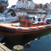
Tubes are finally installed!
I didn't take very good photos of the last steps, but will attempt to describe what I learned:
Transom Reinforcement:
Additional pieces were cut and glued over the two original reinforcement bits. Before gluing the overlap pieces in place, I did a little back-filling with Sikaflex, not with any structural aspirations, but rather to avoid having any hollow places for water to accumulate. Overall, the pieces all went together quite well.
Underside Strips:
To deal with the step from the underside flange onto the tube, I pulled a wide popstickle (~10mm radius) fillet with sikaflex. This was a bit of a pain as it required more taping off and cleanup but made a nice and smooth transition without sacrificing much bonding area on the tube. These strips went on pretty easily although I continue to be amazed just how long this process takes. It seems like gluing on a few strips should take an hour or so when it actually took two more days...
Same deal, marking, taping off, applying 3 layers of glue to each side (thinning the glue with Toluene made this much easier).
Someone recommended trimming back the cheap-o brushes to 1/2 length for spreading the glue which worked quite well except for the inability of the brush to carry much glue when applying overhead.
Once the 6 underside strips were applied (starting at the transom for the correct overlap), I templated and cut another patch to overlap the bow strips. I have come across two stories of failure in this area from slamming into waves, so I made this patch rather large and took a lot of care bonding it down. The fiberglass flange was actually broken on my boat so when I re-built it, I staggered in a few extra layers.
So far, I have only glued on one continuous strip of rub-rail all around the tubes. Again, pretty straightforward. Prepping the tubes and rubrail took a little while but I have got a new 6" large stroke DeWalt orbital sander which works well with 60-grit on the tubes and even 40-grit on the rubrail. Starting at the port-side transom, we worked in about 6'ft increments, using aluminum foil on the tubes to create a working area for applying glue to the rail w/o getting it onto the tubes. A lot of pressure in the tubes helped getting the rail down, especially around the bow, and some careful trimming around the transom made for a nice and clean end. I think the most difficult thing about this process is taking the time to clean off excess glue on the tubes since there has to be a slightly larger area prepped on the tubes to give some tolerance when sticking the rail down.
One more note regarding the rubrail:
I had issues with rubrail separating from the tubes bear the transom where they are submerged part of the time and see a lot of spray. After three clean-ups and re-gluing sessions, i switched to stabond adhesive from the NRS hypalon glue. That works much better as the rubrail is not hypalon.
Hi, I met you/admired your boat in CI harbor by the boat yard about 1 1/2 years ago (I am a harbor patrol officer). Anyway, I just bought a searider 5.4 of my own and would appreciate the chance to show it to you and talk projects. 805-766-6209.