|
|
 03 May 2011, 20:35
|
#1
|
|
Member
Country: UK - Scotland
Town: Aberdeenshire
Boat name: Sula
Make: Ribcraft 4.8m
Length: 4m +
Engine: Tohatsu 70hp + aux
MMSI: 235087213
Join Date: Jun 2007
Posts: 4,531
|
Wiring a RIBcraft 4.8m
After picking up my new boat last year, I'm slowly crossing off the jobs still to do, and the dreaded electrics is last on my list. The boat has under-deck trunking, so all the cables to and from the engine are out of sight. The entry/exit point is within the console for connection to the battery, etc.
If anyone can point me in the general direction (regards wiring) I'd appreciate it.
The engine is a 2006 Tohatsu 60hp (2-stroke) PTT. It's now mounted. Throttle and gear shift cables still to install - that's for this weekend, along with fuel connections.
What I plan to install:
1/ 12v battery in battery-box secured in the console
2/ Fit Tohatsu trim guage and tacho (I'll cut holes in the console once I've tested them)
3/ Extend battery cables (current cables are too short)
4/ Install battery isolator switch
5/ Install rocker switches/fuse panel
6/ Fit Perko light pole
7/ Fit DSC VHF radio and antenna
The trim and tacho gauges look straight forward as they have wiring looms and connect either to the throttle control or direct from the engine.
Where do I start? From the 12v battery, do I connect directly to the battery isolator switch, and from that to the fuse panel, etc. Also what gauge of wire do I need. 
__________________
|

|

|
|
03 May 2011, 21:01
|
#2
|
|
Member
Country: UK - England
Town: London
Make: Ribcraft
Length: 8m +
Engine: 250hp
Join Date: Jan 2011
Posts: 196
|
First of all let's not make things too complicated, outboard wiring must be a separate job.
From Outboard you generally need to connect it directly to your Battery (or if you have Isolator) for Positive and Negative is connected in the same way but just directly between the battery's negative point and the outboard.
You must check the wiring diagram for the outboard to make sure there is a fuse already built in. If not, you must check the starting current and put a High Amp fuse between the positive connection. That depends on the starting current, DO NOT install a very High Amp fuse as it could possibly damage your outboard and again if you install a low amp fuse it could just burn every time you try to start the engine (I assume it is electric start??).
Once you have done the wiring for the outboard, CHECK that the outboard is charging the battery. You need a Voltmeter. The battery voltage must read about 11.9-13V before starting the engine and about 30sec after the engine is started it should go about 14V.
So far you have completed the wiring for the outboard.
Then you need a Distribution Terminal for VHF, GPS, Nav Lights etc.. One Thick High Amp Cable should be connected to your Battery's positive node (or Battery Isolator) and then connect it to the terminal. Other electronics must be supplied from the Terminal.
You must have fuse between Positive connections of ALL electronics and Lights etc. and the Terminal. Most of these devices come with an appropriate fuse in their package so use exactly that fuse.
For negative connection of the electronics you again need another terminal. Same procedure but without the in-line fuse. DO NOT connect the negatives to the battery's negative node as it will be messy.
If you have expensive GPS or Plotter etc. with LCD you may consider a Voltage Regulator as in case your outboard is overcharging the battery it does not damage those gadgets.
__________________
|
|
|
|
|
03 May 2011, 22:10
|
#3
|
|
Member
Country: UK - Scotland
Town: Aberdeenshire
Boat name: Sula
Make: Ribcraft 4.8m
Length: 4m +
Engine: Tohatsu 70hp + aux
MMSI: 235087213
Join Date: Jun 2007
Posts: 4,531
|
Thanks Vandad. 
Quote:
|
From Outboard you generally need to connect it directly to your Battery (or if you have Isolator) for Positive and Negative is connected in the same way but just directly between the battery's negative point and the outboard.
|
Forgive me if I'm recapping here - but it's just so I'm 100% sure. I am planning to connect an isolator switch between the outboard and the battery. The (+) cable from the engine goes direct to the isolator. And the (-) cable from the engine goes direct to battery (-) terminal?
Quote:
|
You must check the wiring diagram for the outboard to make sure there is a fuse already built in. If not, you must check the starting current and put a High Amp fuse between the positive connection. That depends on the starting current, DO NOT install a very High Amp fuse as it could possibly damage your outboard and again if you install a low amp fuse it could just burn every time you try to start the engine (I assume it is electric start??).
|
I've checked this. The engine has a 20amp inline fuse already installed.
Quote:
|
Once you have done the wiring for the outboard, CHECK that the outboard is charging the battery. You need a Voltmeter. The battery voltage must read about 11.9-13V before starting the engine and about 30sec after the engine is started it should go about 14V.
|
The battery reads 13v just now prior to starting. I'll double-check it again once it's running.
Quote:
|
Then you need a Distribution Terminal for VHF, GPS, Nav Lights etc.. One Thick High Amp Cable should be connected to your Battery's positive node (or Battery Isolator) and then connect it to the terminal. Other electronics must be supplied from the Terminal.
|
What are we talking about here, 45amp 10mm wire for example? So connect this wire from the (+) battery terminal to the (+) terminal on the isolator?
Quote:
|
You must have fuse between Positive connections of ALL electronics and Lights etc. and the Terminal. Most of these devices come with an appropriate fuse in their package so use exactly that fuse. For negative connection of the electronics you again need another terminal. Same procedure but without the in-line fuse. DO NOT connect the negatives to the battery's negative node as it will be messy.
|
I'm assuming this is where the fuse panel and rocker switches comes in? How does the fuse panel connect? Do you run a high-amp wire (+) from the fuse panel to the battery isolator (+), and then run another high amp wire (-) from the fuse panel direct to the (-) battery terminal?
__________________
|
|
|
|
|
04 May 2011, 03:30
|
#4
|
|
Member
Country: UK - England
Town: South Yorks
Boat name: Black Pig
Make: Ribcraft
Length: 5m +
Engine: DF140a
MMSI: 235111389
Join Date: Feb 2008
Posts: 11,883
|
Quote:
Originally Posted by Vandad

You must check the wiring diagram for the outboard to make sure there is a fuse already built in. If not, you must check the starting current and put a High Amp fuse between the positive connection. That depends on the starting current, DO NOT install a very High Amp fuse as it could possibly damage your outboard and again if you install a low amp fuse it could just burn every time you try to start the engine (I assume it is electric start??).
|
Are you sure about that?
__________________
Rule#2: Never argue with an idiot. He'll drag you down to his level & then beat you with experience.
Rule#3: Tha' can't educate pork.
Rule#4: Don't feed the troll
|
|
|
|
|
04 May 2011, 07:42
|
#5
|
|
Member
Country: UK - England
Town: Salcombe, Devon, UK
Boat name: BananaShark
Make: BananaShark
Length: 10m +
Engine: 2xYanmar 260 diesels
Join Date: Mar 2003
Posts: 4,225
|
I would never fit a fuse in the starter feed and would also never extend those wires but fit new one piece ones.
__________________
Cookee
Originally Posted by Zippy
When a boat looks that good who needs tubes!!!
|
|
|
|
|
04 May 2011, 09:45
|
#6
|
|
Member
Country: UK - England
Town: Preston
Boat name: Katy Blue/Banana Yuk
Make: Ribcraft / Mirror
Length: 5m +
Engine: Suzuki DF90
MMSI: 235086157
Join Date: May 2004
Posts: 64
|
Here's my fuse panel
At the risk of being shot down in flames, here's my fuse board (DIY in 5.45m Ribcraft) .
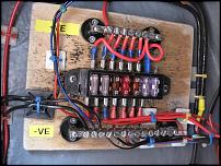
The actual fuse-box cover is removed. This one covers all the non-engine aspects only, i.e. radio, sounder, lights, bilge pump, compass illumination, fuel gauge and possibly something else I can't remember right now. The car-type fuse holder came from Halfords, and the positive and negative bars came from IIRC Index Marine. I have no idea why I used differing length bars. 2A blade fuses aren't the easist to find; obviously I used 3A! Proper ratchet crimps make more reliable crimps on the spade connectors. And those square stick-on cable tie attachments work well to keep things tidy. Arm yourself with hundreds of small cable ties - I ended up wasting lots as the loom sizes grew during fitting. The power supply to this board is taken from the left side of the bars to the battery - except the positive lead is 'split' by one of those console mounted £10 plastic key isolator thingies which has easily been the least reliable part. I later made a bridging lead to use on those days it decides not to make contact. With hindsight the main power supply cables could probably have been beefier. All finally sprayed with some Halfords damp seal type stuff, and apart from the isolator, all has worked well for 10 years or so. Next time around I'd strive to be even neater and spread the stuff out slightly more. I'm sure there's much better out there - but it's a start ...
__________________
Regards, Neil R
|
|
|
|
|
04 May 2011, 12:34
|
#7
|
|
Member
Country: UK - England
Town: Salcombe, Devon, UK
Boat name: BananaShark
Make: BananaShark
Length: 10m +
Engine: 2xYanmar 260 diesels
Join Date: Mar 2003
Posts: 4,225
|
A better but more expensive solution is to use the heatshrink connectors that have hot glue in them - it seals the end of the wire. The wire we use is marine grade which doesn't go black in time and will outlast the plain copper wire many times over.
__________________
Cookee
Originally Posted by Zippy
When a boat looks that good who needs tubes!!!
|
|
|
|
|
04 May 2011, 14:28
|
#8
|
|
Member
Country: UK - Scotland
Town: Aberdeenshire
Boat name: Sula
Make: Ribcraft 4.8m
Length: 4m +
Engine: Tohatsu 70hp + aux
MMSI: 235087213
Join Date: Jun 2007
Posts: 4,531
|
Quote:
Originally Posted by Neil R
At the risk of being shot down in flames, here's my fuse board (DIY in 5.45m Ribcraft).
|
Great stuff.
__________________
|
|
|
|
|
04 May 2011, 17:08
|
#9
|
|
Member
Country: UK - England
Town: Kings Lynn
Boat name: Blow 'N' Away
Make: Coastline
Length: 7m +
Engine: Suzuki 175
Join Date: Jun 2009
Posts: 503
|
Quote:
Originally Posted by Cookee
A better but more expensive solution is to use the heatshrink connectors that have hot glue in them - it seals the end of the wire. The wire we use is marine grade which doesn't go black in time and will outlast the plain copper wire many times over.
|
Is the Marine cable ' tinned', do you use multi strand or single strand cable?.
__________________
|
|
|
|
|
04 May 2011, 20:46
|
#10
|
|
Member
Country: UK - Channel Islands
Town: A large rock
Boat name: La Frette
Make: Osprey Vipermax
Length: 6m +
Engine: 200 Suzzy
Join Date: May 2004
Posts: 2,893
|
As Vandad says, you want to keep the outboard cables independant from the 'domestic' supply. You probably need 25mm2 cable at most to feed the starter on the outboard. the longer teh cable run the larger the cable needs to be to avoid voltage drop. I would suggest a good battery switch (BEP or Hella Marine) in the positive cable somewhere near the battery. The starter draws a huge current so any smaller cross section of cable may get warm and reduce voltage supply to the starter. The negative cable will be unswitched and connected straight to the battery -'ve terminal. From the switched side of your battery switch you can then run a second cable to your fuse/distribution board. A 5mm cable would be quite adequate here given the short lengths involved and lower power requirements. Obviously the negative from the -'ve buss needs to be 5mm too. You can then wire each of your navigatin instruments to a separate fuse on the distrubution panel. All negatives will be connected to a common buss for convenience. Neil R's picture illustrates this quite well.
I always use multistrand tinned marine cable and good quality adhesive lined heatshrink connectors for the important items.
Photo shows my wiring half way through fit out
|
|
|
|
|
05 May 2011, 07:06
|
#11
|
|
Member
Country: UK - England
Town: Salcombe, Devon, UK
Boat name: BananaShark
Make: BananaShark
Length: 10m +
Engine: 2xYanmar 260 diesels
Join Date: Mar 2003
Posts: 4,225
|
Quote:
Originally Posted by Paul Cannell
Is the Marine cable ' tinned', do you use multi strand or single strand cable?.
|
Yes Marine grade cable is "Tinned" and multi strand as Erin says. The heatshrink and glue connectors also support the cable better at the entry point to the connector.
I would expect car stuff to last no more than two to three years if left alone and subject to any salt water contamination - using water repelling sprays can stretch this out longer but there is no substitute for quality!
__________________
Cookee
Originally Posted by Zippy
When a boat looks that good who needs tubes!!!
|
|
|
|
|
05 May 2011, 18:29
|
#12
|
|
Member
Country: UK - England
Town: London
Make: Ribcraft
Length: 8m +
Engine: 250hp
Join Date: Jan 2011
Posts: 196
|
Quote:
Originally Posted by Pikey Dave
Are you sure about that?
|
Yes!
Say if you install a 1amp fuse and the starter has a starting current of 1.2amp then it will blow up the fuse.
Again, say if there was a short circuit within the starter's circuit and you had installed a 50amp fuse, it will draw 50amp fault current until the fuse it blown. This can damage a lot of instruments especially in new outboards with ECU, mainly measurement units are so sensitive to high currents.
__________________
|
|
|
|
|
05 May 2011, 21:17
|
#13
|
|
Member
Country: UK - England
Town: South Yorks
Boat name: Black Pig
Make: Ribcraft
Length: 5m +
Engine: DF140a
MMSI: 235111389
Join Date: Feb 2008
Posts: 11,883
|
Quote:
Originally Posted by Vandad
Yes!
Say if you install a 1amp fuse and the starter has a starting current of 1.2amp then it will blow up the fuse.
Again, say if there was a short circuit within the starter's circuit and you had installed a 50amp fuse, it will draw 50amp fault current until the fuse it blown. This can damage a lot of instruments especially in new outboards with ECU, mainly measurement units are so sensitive to high currents.
|
You'd be looking at something close to a 200A+(depending on engine size)fuse for a starter circuit. It doesn't happen, trust me 
__________________
Rule#2: Never argue with an idiot. He'll drag you down to his level & then beat you with experience.
Rule#3: Tha' can't educate pork.
Rule#4: Don't feed the troll
|
|
|
|
|
05 May 2011, 23:08
|
#14
|
|
Member
Country: UK - Scotland
Town: Aberdeenshire
Boat name: Sula
Make: Ribcraft 4.8m
Length: 4m +
Engine: Tohatsu 70hp + aux
MMSI: 235087213
Join Date: Jun 2007
Posts: 4,531
|
Any recommendations for where to source new battery cables? The existing battery cables are too short, so I need to replace them with a set of new cables and ends. I'm already over-budget, so looking for the most cost-effective way to do it. Current cables are 25mm2 (170amp/70°C). Probably need 4.5m lengths. Does the cable have to increase in diameter given length?
These guys seem reasonable, considering it's the tinned marine variety: https://www.electricalcarservices.co...25-p-1488.html
__________________
|
|
|
|
|
05 May 2011, 23:18
|
#15
|
|
Member
Country: UK - Wales
Town: West Wales
Make: Vipermax 5.8, SR4.7
Length: 5m +
Engine: 150 Opti, F50EFi
Join Date: Sep 2005
Posts: 6,299
|
Welding cable.
__________________
|
|
|
|
|
06 May 2011, 06:37
|
#16
|
|
Member
Country: UK - England
Town: South Yorks
Boat name: Black Pig
Make: Ribcraft
Length: 5m +
Engine: DF140a
MMSI: 235111389
Join Date: Feb 2008
Posts: 11,883
|
Quote:
Originally Posted by Downhilldai
Welding cable. |
Yup! can't beat welding cable. The good stuff is usually tinned as well. I'd go for 30 or 35mm2. Use good quality clamps at the battery end, don't use wing nuts on the battery clamps, use Nylocs or plain nuts with star washers. If it was me, I'd solder the lugs onto the motor end & then use heatshrink or self amalgamating tape over the joint between the insulation & the lug. Any welding suppliers will supply you short lengths of cable.
Oh & BTW, don't put any fuses in it
__________________
Rule#2: Never argue with an idiot. He'll drag you down to his level & then beat you with experience.
Rule#3: Tha' can't educate pork.
Rule#4: Don't feed the troll
|
|
|
|
|
06 May 2011, 07:07
|
#17
|
|
Member
Country: UK - England
Town: Salcombe, Devon, UK
Boat name: BananaShark
Make: BananaShark
Length: 10m +
Engine: 2xYanmar 260 diesels
Join Date: Mar 2003
Posts: 4,225
|
Quote:
Originally Posted by Vandad
Yes!
Say if you install a 1amp fuse and the starter has a starting current of 1.2amp then it will blow up the fuse.
Again, say if there was a short circuit within the starter's circuit and you had installed a 50amp fuse, it will draw 50amp fault current until the fuse it blown. This can damage a lot of instruments especially in new outboards with ECU, mainly measurement units are so sensitive to high currents.
|
I build boats for a living and I would like to know where you have got this information from - clearly I have been rigging my race boats and RIBs all wrong for years!
__________________
Cookee
Originally Posted by Zippy
When a boat looks that good who needs tubes!!!
|
|
|
|
|
06 May 2011, 08:24
|
#18
|
|
Member
Country: UK - Channel Islands
Town: A large rock
Boat name: La Frette
Make: Osprey Vipermax
Length: 6m +
Engine: 200 Suzzy
Join Date: May 2004
Posts: 2,893
|
There will be a fuse in your motor, (50amp in mine IIRC) but this is nothing to do with the starter motor it is for the ancillary electrics, ecu etc. On inboard installations there is a tendancy to fit a large fuse for the starter current (450amp on a 265 inboard I know of) but I have never seen one on an outboard installation. Not to say it wouldn't harm having one though.
|
|
|
|
|
06 May 2011, 08:31
|
#19
|
|
RIBnet supporter
Country: UK - England
Town: Rutland
Length: no boat
Join Date: May 2006
Posts: 2,500
|
Quote:
Originally Posted by Erin
There will be a fuse in your motor, (50amp in mine IIRC) but this is nothing to do with the starter motor it is for the ancillary electrics, ecu etc. On inboard installations there is a tendancy to fit a large fuse for the starter current (450amp on a 265 inboard I know of) but I have never seen one on an outboard installation. Not to say it wouldn't harm having one though.
|
You have now
__________________
|
|
|
|
|
06 May 2011, 11:08
|
#20
|
|
Member
Country: UK - Channel Islands
Town: A large rock
Boat name: La Frette
Make: Osprey Vipermax
Length: 6m +
Engine: 200 Suzzy
Join Date: May 2004
Posts: 2,893
|
Very good, and a shunt for a battery meter too. Proper installation.
|
|
|
|
|
|
 Posting Rules
|
You may not post new threads
You may not post replies
You may not post attachments
You may not edit your posts
HTML code is Off
|
|
|
|
 Recent Discussions
 |
|
|
|
|
|
|
|
|
|
|
|
|
|
|
|
|
|
|
|
|
|
|
|
|
|
|
|
|
|
|
|
|
|


 Sula
Sula BLACK PIG
 Piglet